Soil strength depends on the effective stresses acting between mineral grains — not the total stresses. A direct shear box can only impose one stress path; a triaxial cell can impose almost any. That's why every modern geotechnical practice calibrates its design strengths on triaxial data.
This guide covers the three workhorse triaxial procedures — CD, CU, and UU — end-to-end. By the end, you will:
- understand the apparatus from cell to drainage line;
- know exactly which test to pick for which problem;
- follow the lab procedure step-by-step;
- interpret the data with Mohr circles to extract c′, φ′, or Su;
- reproduce the analysis in three lines of Python using
GeoEq's
ge.triaxial().
The apparatus
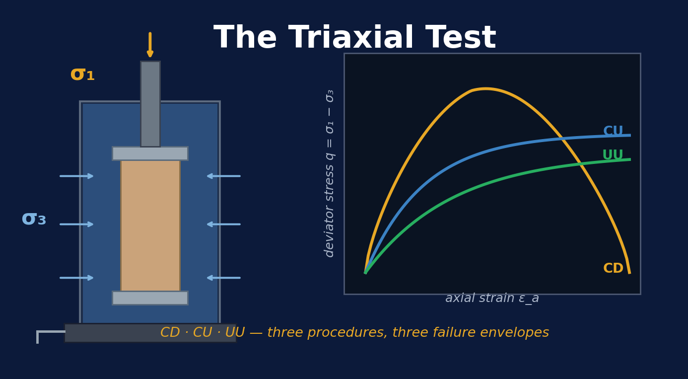
A triaxial cell is a thick-walled cylinder of clear acrylic or polycarbonate, sealed at top and bottom, filled with water (or silicone oil). The soil specimen sits inside:
- Cylindrical specimen — usually 38 mm diameter × 76 mm height (a 2:1 height-to-diameter ratio prevents end-effects from controlling failure).
- Rubber membrane stretched over the specimen and sealed to the top cap and base pedestal with O-rings. The membrane isolates the specimen from the cell fluid while transmitting the confining pressure to it.
- Porous stones at the top and base allow water to drain in or out of the specimen.
- Drainage line connects the base porous stone to a pore-pressure transducer or volume-change device through a valve.
- Piston passes through the top of the cell to apply the axial load. The deviator stress q = σ1 − σ3 is the axial stress over and above the confining pressure.
- Cell pressure system — usually a hydraulic pressure pot or compressed-air bladder — applies the all-round confining pressure σ3.
Three procedures, three drainage states
All three procedures use the same apparatus. The difference is when the drainage valve is open. That single choice controls whether the specimen can change volume during loading, whether excess pore pressure builds up, and which strength parameters you measure.
UU — Unconsolidated-Undrained
The fastest test. The specimen is mounted, the cell pressure applied, and the specimen is sheared immediately. The drainage valve is closed the whole time. No consolidation, no measurement of pore pressure. The result is the undrained shear strength Su = (σ1f − σ3) / 2.
- Time: 30–60 minutes per specimen.
- Drainage valve: closed throughout.
- What you get: Su (undrained shear strength). φu = 0 by definition for saturated clays.
- Used for: rapid loading on saturated clays where pore pressures cannot dissipate during the design event (embankment placement, foundation construction).
CU — Consolidated-Undrained (with pore-pressure measurement)
The specimen is mounted, the cell pressure applied, then the drainage valve is opened to allow the specimen to consolidate under the cell pressure. Once primary consolidation is complete (verified with a Δu = 0 reading on the transducer), the valve is closed, and the specimen is sheared while measuring pore pressure.
- Time: 1–3 days per specimen.
- Drainage valve: open during consolidation, closed during shear.
- What you get: both total-stress parameters ccu, φcu and effective-stress parameters c′, φ′ (from pore-pressure measurements).
- Used for: most clay strength characterisation in practice. Faster than CD and gives the same effective-stress envelope.
CD — Consolidated-Drained
Consolidation phase identical to CU. During shear the valve stays open, so the loading rate must be slow enough that excess pore pressure never develops (Δu = 0 throughout). The specimen is free to change volume — densifying or dilating as the stress state evolves.
- Time: 2–7 days per specimen (rate-controlled by drainage).
- Drainage valve: open throughout.
- What you get: c′, φ′ directly. Volumetric strain εV recorded throughout.
- Used for: sands always; clays when long-term effective-stress strength is the design case (slope stability years after construction).
Try it — run the three tests yourself
Pick a test type, set the confining pressure and the soil density, and hit ▶ Run test. The piston descends, the specimen deforms, and the stress–strain curve traces out in real time. The secondary plot shows volume change (for CD) or excess pore pressure (for CU and UU). When the test finishes, click + Add to envelope to drop a Mohr circle on the panel to the right. Repeat at three confining pressures and the failure envelope draws itself.
Lab procedure, step by step
The recipe below works for all three procedures. The branches at steps 5 and 7 show where they differ.
1. Prepare the specimen
- Trim a cylindrical specimen from the undisturbed sample at 2:1 height-to-diameter ratio (typically 38 × 76 mm).
- Measure the initial mass, height, and diameter to 0.1 mm.
- Take a moisture-content sample from the trimmings for parallel measurement of w0.
2. Mount the specimen
- Place a saturated porous stone on the base pedestal, then a filter-paper disc on top.
- Carefully set the specimen on the filter paper. Add another filter disc and the upper porous stone.
- Stretch a rubber membrane over the specimen using a membrane stretcher and seal it to the top cap and base pedestal with O-rings.
- Install the top cap with the loading-piston ball-seat.
3. Assemble the cell
- Lower the cell over the specimen and bolt the cell head to the base.
- Fill the cell with de-aired water. Bleed all air through the top vent.
- Connect the drainage line to the base pedestal port and the cell-pressure line to the cell-head port.
4. Saturate (B-test)
For clay specimens or any case where suction may be present, run a back-pressure saturation cycle:
- Apply a small cell pressure (10–20 kPa) and an equal back pressure to the drainage line.
- Open the drainage valve and let the specimen draw in water until any air bubbles dissolve.
- Close the valve. Increment cell pressure by a known step Δσ3 (say 50 kPa) and read the resulting Δu.
- Compute Skempton's B-coefficient: B = Δu / Δσ3.
- Saturation is acceptable when B ≥ 0.95. If B is lower, raise back pressure by another 50 kPa and repeat.
5. Consolidate (CD & CU only — skip for UU)
- Set the confining pressure σ3 to the target value for the test.
- Open the drainage valve.
- Record the volume change (CD) or the dissipating pore pressure (CU) over time.
- Wait for primary consolidation to complete — typically when t90 on a √t plot is reached, or Δu ≤ 5% of the increment.
6. Set the shear rate
The right rate depends on the procedure and the specimen drainage path:
- UU — fast: 0.5–1 % strain per minute. About 30 min total.
- CU — moderate: rate set so excess pore pressure stays uniform across the specimen. Typically 0.05–0.1 % strain per minute for clays.
- CD — slow: rate set so the specimen can drain freely. From t100 of the consolidation phase, εf·15 / t100 is a rule-of-thumb upper bound (Bishop & Henkel 1962). Often 0.005–0.02 % per minute.
7. Shear the specimen
- CD: drainage valve open. Start the piston. Record axial force, axial strain, and volume change. Continue until εa ≈ 15 % or until a clear peak followed by post-peak strain-softening is observed.
- CU: drainage valve closed. Same recordings plus pore-water pressure. Continue until εa ≈ 15 % or peak is reached.
- UU: drainage valve closed. Same as CU but skip the consolidation phase entirely.
8. Unload and document
- Stop the loading. Drain the cell.
- Remove the specimen, measure its post-test height and weigh it.
- Cut and photograph the failure plane. Document the failure mode (single shear plane, conical, barrel).
From data to parameters
At failure, the principal stresses are σ1f = σ3 + qf (axial) and σ3 (radial). The Mohr circle of stress at failure has:
- centre at (σ1f + σ3) / 2 on the σ-axis;
- radius (σ1f − σ3) / 2 = qf / 2.
Run three tests at three different confining pressures, draw all three Mohr circles, and the Mohr-Coulomb failure envelope is the common tangent. Its slope is tan φ′ and its τ-axis intercept is c′.
For CU tests, you can plot two envelopes — one using total stresses (gives ccu, φcu) and one using effective stresses (gives c′, φ′). The effective-stress envelope is the "real" strength of the soil; the total-stress envelope is a shortcut for undrained loading analyses.
Working it in Python with GeoEq
GeoEq's ge.triaxial() takes the confining pressures and
deviator stresses at failure for three (or more) tests and returns
c′ and φ′ — exactly the operation you'd do by hand with Mohr circles
and a straight-edge.
import geoeq as ge

# Three CD triaxial tests on the same soil at increasing sigma_3
sigma3       = [100, 200, 300]                  # kPa
delta_sigma  = [180, 280, 380]                  # q_f at each test

res = ge.triaxial(sigma3=sigma3,
                    delta_sigma=delta_sigma,
                    kind="CD")

print(res)
# {'c': 10.0, 'phi': 28.5, 'sigma1': [280, 480, 680]}
For a UU test on a saturated clay, the deviator stress at failure is nearly identical regardless of σ3 (because all the increased cell pressure goes straight into pore pressure):
# A UU test directly gives undrained shear strength
res = ge.unconfined(qu=180)
print(res)
# {'Su': 90.0}     -- equivalent to q_u / 2
For a complete bearing-capacity or settlement analysis that feeds these results back into a footing design, see the bearing-capacity methods comparison.
When to pick which test
| Design scenario | Best test | Why |
|---|---|---|
| Sand foundation (always drained) | CD | Effective-stress strength is the only thing that matters; no pore-pressure complications. |
| Fast embankment loading on clay | UU | The undrained Su controls. Construction happens too fast for drainage. |
| Long-term slope stability on clay | CD or CU | Effective-stress envelope governs years after construction. |
| Earthquake liquefaction screening | Cyclic CU | Need to measure pore-pressure build-up under cyclic loading. |
| Triaxial as input to FEA | CU | Provides both total and effective parameters from one specimen set. |
Common pitfalls
- Failure to saturate — if B < 0.95 on a CU/UU test, pore-pressure readings under-report the real value, and the effective-stress envelope is biased to the high side. Always check B.
- Shearing too fast in CD — generates excess pore pressure inside the specimen even though the burette shows no volume change. Result: the "drained" envelope is actually partially undrained.
- End-platen friction — for short specimens (h/d < 2), the platens restrain the ends and the failure mode is conical rather than shear-plane. Use 2:1 or use lubricated end caps.
- Membrane stretching at low σ3 — at very low confining pressures the rubber membrane contributes to the apparent stiffness. Correct using ASTM D4767 Section 11.4.
- Reading the peak too early in CU — for some normally-consolidated clays the peak is at the point of maximum (q/p′) ratio, not maximum q. Plot both and pick consistently.
What to read next
- Bearing capacity methods compared — how to use c′ and φ′ from your triaxial tests in a foundation design.
- Liquefaction triggering, simplified — when cyclic CU tests are required.
- The three-phase soil system — the volume change you saw on a CD test is exactly the void volume changing.
- Full lab-testing reference in the docs — every shear-strength function, including
ge.direct_shear,ge.unconfined, andge.mohr_circle.